Summary of relevant knowledge of worm and worm gear
TIME:2021-10-20
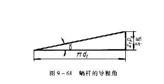
Worm gear is used for rotation between two cross shafts (the cross angle is generally right angle). Usually, the worm is driven and the worm gear is driven. It is used for deceleration to obtain a large transmission ratio.
In worm and worm gear transmission (Fig. 9-60), the most commonly used worm is cylindrical Archimedes worm. The axial tooth profile of this worm is a straight line, and the axial section is isosceles trapezoid, which is similar to trapezoidal thread. The number of teeth of the worm is called the number of heads, which is equivalent to the number of threads of the thread. It is usually single head or double head.
The worm is equivalent to a helical cylindrical gear, and its teeth are distributed on the annular surface, so that the gear can wrap the worm to improve the contact condition, which is a feature of the worm gear shape.
(1) Calculation of main parameters and dimensions of worm gear
1. Pitch P and modulus p
In the middle plane containing the worm axis and perpendicular to the worm gear axis (Fig. 9-60), the axial tooth pitch P of the worm shall be equal to the end face tooth pitch P of the worm gear (P = P = P), so the axial modulus m of the worm and the end face modulus M of the worm gear are also equal (M = M = m), and are specified as standard modulus. The worm indexing circle diameter D, throat circle diameter D and tooth root circle diameter D are measured in the middle plane.
2. Worm diameter coefficient Q
Worm diameter coefficient is an important parameter unique to worm, which is equal to the ratio of worm indexing circle diameter D to axial modulus m, that is, q = D / m or D = MQ
Corresponding to different standard modulus, the corresponding Q value is specified. The purpose of introducing this coefficient is mainly to reduce the number of machining tools.
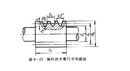
3. Lead angle R
Unfold along the indexing cylindrical surface of the worm, and the helix develops into an inclined straight line, as shown in figure 9-61. The included angle R between the inclined line and the bottom line is called the lead angle of the worm. When the worm diameter coefficient Q and the number of heads Z are selected, the lead angle R is uniquely determined. The relationship between them is tan
For a pair of mutually toothed worm and worm gear, except that the modulus and tooth shape angle must be the same respectively, the worm lead angle R and 2 worm gear rotation angle B shall be the same in size and direction, i.e. r = B.
The dimensions of each part of worm and worm gear are related to module m, worm diameter coefficient Q, lead angle R and number of teeth Z and Z. see table 9-15 for the specific relationship.
(2) Drawing method of worm and worm gear
1. Drawing method of worm
Generally, a view is selected for the worm, and the drawing method of its tooth top line, tooth root line and graduation line is the same as that of the cylindrical gear system, as shown in Fig. 9-62. The tooth root line represented by thin lines in the figure can also be omitted. The tooth profile can be represented by partial view or partial enlarged drawing.
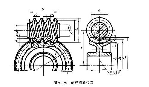
2. Turbine drawing
The drawing method of turbine is similar to that of cylindrical gear, as shown in figure 9-63.
(1) In the view with non-circular projection, full section or half section view is often used, and fine points, circle and symmetrical center line are drawn at the position of the meshing worm axis to indicate the relevant dimensions and center distance.
(2) In the view projected as a circle, only the maximum top circle and indexing circle are drawn, and the throat circle and tooth root circle are omitted. The view projected as a circle can also be replaced by the local view expressing the keyway shaft hole.
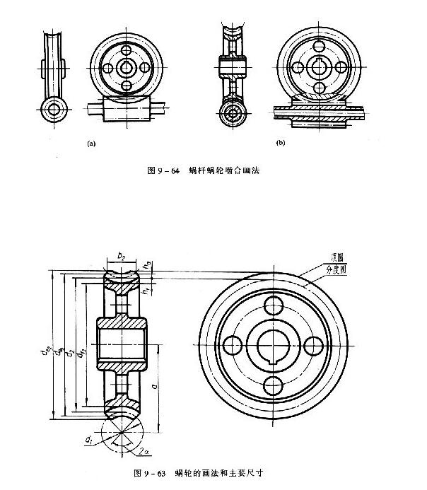
3. Drawing method of worm gear meshing
There are two forms of worm and worm gear meshing: outline drawing and sectional view. The drawing method is shown in figure 9-64. In the view where the worm gear is projected as a circle, the pitch circle of the worm gear is tangent to the pitch line of the worm.